Modification
D) Using a
MMX Interposer and P-233MMX
I wanted to get rid of that stupid
blinking "Under Construction" in first place. Therefore I decided to
write at least something useful at this place. Hope you all
agree.
Let's start with some CPU-basics.
How to differ a MMX-CPU
from a
Non-MMX
It helps if you can read. Since
you are here (at this place) I think
you can. In this case you should study the writing atop the CPU.
Non-MMX Pentium are labelled Intel pentium i200 or i166.
MMX Pentiums are labelled Intel pentium w/ MMXtm
tech
Sometimes you cannot read the writing atop (anymore) or it is blocked
by a heatsink, a glued one for instance, a glued heat-spreader or soild
with thermal grease goo. In this case look at the underside:
Non-MMX Pentiums are labelled intel pentium FV80502xxx SY045/VSU
MMX-Pentium are labelled intel pentium w/ MMX tech FV80503xxx
SL27J / 2.8V
xxx can be 166, 200 or 233 - whatever speed rating they'd used. The
SY...
indicates a 3.3V processor, the SJ... is a dual-rail MMX, where "2.8V"
gives the core voltage for the second (inner) plane. The external
interface runs at 3.3V in either case.
MMX CPU usually had the plastic case with the small silver heat
spreader - but not always. I have seen a few all-ceramic types with
white lettering, but the "MMX tech" is always clearly visible, on top
as well as on the underside.
That should suffice to differ the two.
Warning: Never try to install a
Pentium MMX CPU on the P90 platform directly !
Its processor core runs at a lower voltage and it gets overheated and
ruined before your system has finished POST most likely. For the MMX
types you need a special adapter with a secondary power regulator,
which reduces the core voltage to an appropriate level. One of these
adapters is the Madex 486007 adapter. It consists of two parts: 1. the
socket adapter for the CPU itself and 2. an external switchmode
regulator, which is directly connected to the main power supply to put
out the required 3.5 - 4.5 Amps at 2.8V for the MMX CPU core.
They are connected with two 4-pin
plugs (blue cables) and the regulator
is connected with another 4-pin 3.5" FDD-style DC-plug to the main
power supply. The regulator has 4x DIL-switch (right from the heatsink)
and can be programmed
to the corresponding core voltage. The large golden heatsink and a
fixing clip
- unfortunately for a wider Socket-7 board only - could be ordered
separately
and were not part of the base kit itself.
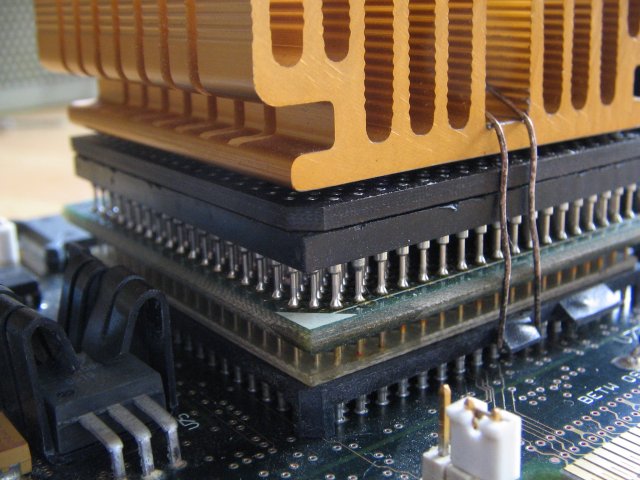
The socket part needs to be carefully installed on the
platform socket. It has very thin pins that go into the CPU socket.
These pins tend to bend and break very easy and that will ruin the
party. Not all pins go into the socket however: these that carry the
lower core voltage are fed to the CPU from that intermediate printboard
visible in the picture. No need to route pins further down.
Once you'd installed adapter socket, CPU, regulator and CPU heatsink
the system should come up as normal. There are jumpers on the
adapter socket to set the matching BF0 / BF1 signalling for the core /
bus ratio. On the 60 MHz (unmodified) platform a 1:3 ratio will bring
you to 180 MHz. For a testrun I would suggest to leave the pins open
and try out the combo at the usual 90 MHz processor speed. Then "work
your way upwards" if CPU and platform are capable to run at 210 MHz as
well with a 1:3.5 ratio.
YARM - Yet Another
Regulator Module
Back then, when I collected a lot
stuff for Pentium-1 CPUs I once bought this MMX adapter / regulator
module along with a mainboard (Non-IBM).
This thing is typical for the silly simple approaches people tried to
"make fit" MMX-CPUs on Socket-7 Non-MMX-ready platforms. It consists of
an interposer board that takes off the secondary core voltage from the
3.3-Volt plane and adds jumpers for setting the new core voltage and
the bus / core clock ratio.
For this purpose it has another member of the LT-108x-regulator family
onboard and gets the power from the main power supply via a male-female
device DC-plug, which got a 4-pin 3.5"-FDD-like plug as well to feed
the module.
At least this prevents the onboard 3.3V regulator from getting
overloaded.
However: the whole design is a tad awkward as you can see from the
pictures below.

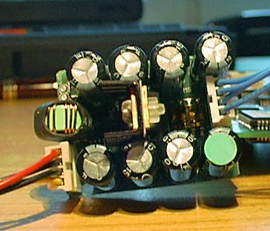
View onto DC-input and the
jumpers ... |

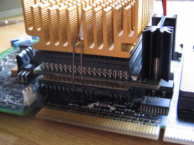
... and how the fixing runs
around the edge. |
|
View from the MCA side upwards |
LT-style regulator with own
heatsink |
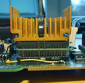
The problem here is, that the
jumpers line up along the one side where
a clip, clamp or "whatever
method" to keep the heatsink on the CPU should go. My construction is
silver wires, tooled along the lower socket hooks
and strapped together inside the heatsink with a nylon cable tie. Usually
this works quite good, but on this adapter the holding wires run around
the edge of the interposer board and - well - barely fit inside the
lower hook. Additionally
this asymmetry pulls the heatsink off-center and I were a bit concerned
on the reliablilty if I would plan to run this thing for longer.
(Which I don't to be honest)
Take this as a "Technology Demonstration": the platform I'd tried it
onto flat out refused to
properly boot with this combo. It complains about a platform change as
usual, but during the refdisk load it dumps into a 0129 1500 error. I'm
not 100-percent sure, but I think the MMX processor I'd used had been
running in a clone board with a 3.3V-core voltage for some time ...
instead of 2.8V as required. I might have accidentially picked it.
Whatever: from the principle it should work and you might get a
similar looking result if you manage to
find one of those regulator-adapters.
Properly and reliably fixing the heatsink might be your biggest
challenge.
Back up to the Top
|