The
importance of cooling certain
components
It is a commonly known phenomenia
that flow of electricity causes heating up components. What we want on
our electric heatings might become a problem in the "silicone world".
With using your fingers hovering over some chips you will find that
some of them grow pretty hot during operation. Some of the
components - namely the voltage regulators and the processor itself -
have heatsinks already to spread the generated heat into the
surrounding air. Some components don't have heatsinks but appear pretty
hot already.
As a "rule of thumb" (not only figuratively) you can do the following
test: wetten your finger a bit and touch the surface of a component. If
the water evaporates immediately it is above 75 degrees Celsius
- and most likely too hot to touch anyway with the bare fingers. Any
temperature below 60°C is not just "nice to touch" but you can
stand it for at least several seconds. If you are capable to keep your
finger on that particular part for much longer (or: very long time) it
will surely be below 50°C.
Not a qualified testing method - and your individual mileage may vary -
but a good quick-test to find out excessive heaters.
As it goes for the silicon chips: the most of them are designed to
operate reliable up to about 115°C at the chip core which
may result in about 75 - 85°C Case Temperature. Also a
common rule here is: the colder - the better.
Every "chip tuner" should be aware of the fact that the attempt to
speed up the board functions will cause more heat. So it is not enough
to rise the clock-frequency and alter the pinout a bit ... and hope
that the technical reserves of the basic design will allow reliable
operation as usual.
Not true.
If you speed up the board clock and if you switch to a
higher-performance processor this will have an influence on the heat
generation. The least you can await is a higher power drawn by the
processor in the first place along with higher power drawn by the
accompanying chips as well - which results in a higher load on the
voltage regulator at least. Which then results in more heat emission of
that part - as well as higher heat emission on the processor itself
compared with the one it substituted.
There you have the first two places already where you need to do
something, where you have to optimize the cooling.
A good reference on how to modify the heatsink for the LT-1084 3.3 Volt
main regulator on the P-90 platform can be found on Jim Shorneys "P90 Complex Page".
Jim has done some major research on that topic and offers some very
good and easy to do modifications there.
Since I am known as one who dislikes to "invent the wheel" any day
again I want to thank Jim for his excellent work and only reference to
his page from here. Thanks Jim.
For the processor there are several good cooling kits available. The
P-90 case is fairly common and still in use for the latest AMD and even
Intel processors that use Socket-7 or Socket 370 or Super-7. The fixing
clips might not fit optimal however - the Socket-5 used a narrower clip
than the later ones or a sort of "Wire Spring" clip. You need to be a
bit inventive and creative here to keep the heatsink on the processor -
which sits on the board facing down.
So just laying it on the processor will not work anyway. You need a
tight fit and some pressure between heatsink and processor case.
 Older processors like the P-90 to P-150 mainly use an
all-ceramic case with a relatively large and flat surface. In terms of
heat distribution this case is however sub-optimal, because ceramic
material keeps the heat inside for longer (low heat transient /
dissipation factor). Older processors like the P-90 to P-150 mainly use an
all-ceramic case with a relatively large and flat surface. In terms of
heat distribution this case is however sub-optimal, because ceramic
material keeps the heat inside for longer (low heat transient /
dissipation factor).
 Later
versions had a ceramic case with a metal (mainly golden) plate inlayed
- the so-called "heat spreader". Unfortunately the heat-spreader and
the case are not of the same height, so that the case itself cannot be
used to distribute heat. The area of the heat spreader is about a half
of that of the entire upper case surface only. In fact the heat
spreader covers the "processor die" only. Later
versions had a ceramic case with a metal (mainly golden) plate inlayed
- the so-called "heat spreader". Unfortunately the heat-spreader and
the case are not of the same height, so that the case itself cannot be
used to distribute heat. The area of the heat spreader is about a half
of that of the entire upper case surface only. In fact the heat
spreader covers the "processor die" only.
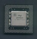 Things came even worser with the introduction of the
Pentium MMX, where Intel started using a plastic case with a thicker,
but smaller heat spreader. Some of the "classical" (Non-MMX processors)
inherited this case as well - like for example the P-166 and the P-200
of the later series. Things came even worser with the introduction of the
Pentium MMX, where Intel started using a plastic case with a thicker,
but smaller heat spreader. Some of the "classical" (Non-MMX processors)
inherited this case as well - like for example the P-166 and the P-200
of the later series.
You are facing two problems here:
- the active area that is capable to disribute the heat from the
processor to the heatsink is rather small
- there is a potential danger to mount the heatsink tilted ....
The other components of the P90 platform get medium warm at least. The
82497 cache controller could be used with those cooling kits designed
for the Pentium 90 which uses side hooks - it has the exact
identical physical size.
A "Socket-7" cooling kit which uses a clip over the heatsink cannot be
used. The 82497 socket lacks the catches typically for Socket-7 where
these clips hook behind.
Problem childs are the 82492 cache RAMs. 10 of them are located on both
sides of the complex card. Fortunately they are physically located one
against the other on both sides, so you could try to get 10
smaller heatsinks (like the one used on earlier revisions of the XGA-2
card RAMDAC) and build yourself 5 pieces of a "C" shaped metal bracket.
Since you need to use thermal conductive grease between
heatsink and cache chip and while this stuff is rather sticky you will
surely manage to affix the two adjacent heatsinks and bring your
self-made clip over the two between the heatsink fins. The clip must
apply some stronger mechanical pressure onto the two heatsinks to press
them together and onto the chips.
Unfortunately I haven't managed to get appropriate heatsinks in the
required amount so far. The heatsinks used on old 4 Mbit Token Ring
adapters might be used - but they have side guides that needed to be
milled down at least, or there is a potential (or: likely) risk that
these guides touch the cache chip outer pinrows.
And BANG ... Apocalypse.
Now ...
... I am known as a person who a) does many things "my way" and b)
likes to recycle items that just lay around.
Since cooling of the CPU and voltage regulator is positively a
topic on the P90 platform I'd found another silly simple solution.
Look here:
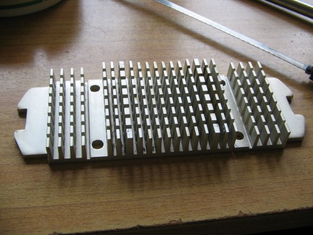
A generic vertical fin Slot-A
heatsink |
Trimmed a bit and nicely fits |
|
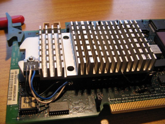
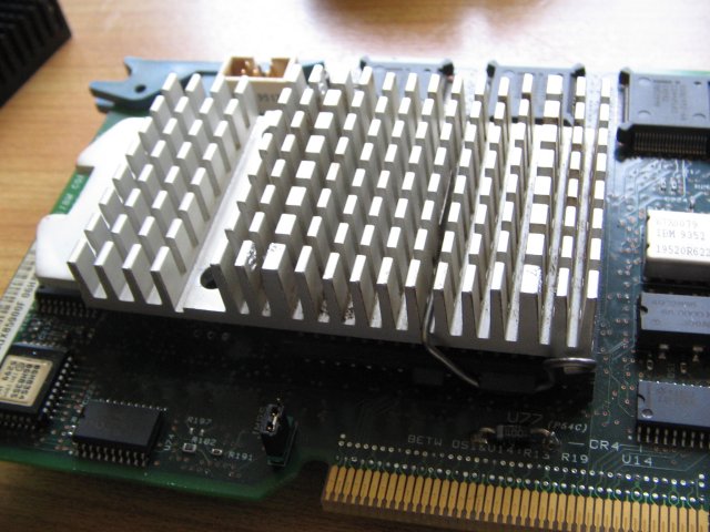
LT1084 regulator added ... |

... and wired down to the
platform |
One day I came across this Slot-A
heatsink. It was still attached to an
Intel Celeron 266MHz CPU, which was of little interest to me. But the
heatsink height nicely matches a Socket 5 CPU like a Pentium-1. A
charming and not unimportant detail is the fact that the heatsink fins
run top down - as required by the airstream from the sidewall fan.
"Hooray !" I cried out and tested how it could be trimmed down for
maximum efficiency. It even had a silicon rubber heat spreader at the
underside - of about the size of a full Pentium case. I decided to trim
off one side along the first row of fins and keep the other side as a
post to fix the regulator to.
As you can see: It looks quite good.
That particular platform had been
considered dead, since it fails to properly POST. In fact the LED panel
stayed entirely dark and I guessed it must be a DC supply problem. But
as a testbed it came handy. So I soldered three wires to the original
regulator position and soldered an original LT1084 regulator at the
other ends. I bended the chip legs upwards and cut them a bit.
Do Not bend the legs too close towards
the case - they will break off !
Use a thin screwdriver and bend the legs around it. Or don't bend them
at all, but make sure not to solder the wires too close to the case.
The heat may damage the chip inside. Leave at least 5mm.
Next I drilled a 2.5mm hole into the heatsink, cut a winding into the
hole, drilled the underside to 6mm, 3mm deep and fixed a M3 lenshead
screw into it. That helps to keep the underside comparatively flat. Not
that it matters - there's room enough. But I have the nut at the upper
side. I used a silicon insulator sheet and a plastic washer under the
nut in case the heatsink gets to GND level by what reason. The
regulator metal plate is connected with the middle pin 2, which carries
the output voltage ... 3.3V in this case.
Then I stuffed a P-133 CPU in the socket, fixed the heatsink /
regulator combo with the genuine IBM heatsink clip to the platform and
installed it in my testbed-95A.
Of course it did not work.
Out of curiosity I'd tested the voltage on the regulator and it were
just about 2VDC. Humma.
After some more testing I found that the pin-2 contact hole must have
been damaged - probably during one of the previous experiments with a
switchmode regulator. I used a little longer wire and fed the regulator
pin 2 (3.3V output) through a left-over hole for the old heatsink
towards the underside of the CPU and there to the marked ends of C177
and C162. These two are the only caps on 3.3V. C210 is at +5V ... Watch
out here !
To my surprise the platform retuned to work.
I did only few and comparatively short tests with this platform so far.
Subjectively the heatsink doesn't get too warm to the touch, but I only
used a P-133 and the platform has got the 66MHz oscillator. So it runs
at 133MHz, even though the cache-RAMs and the cache controller are only
60MHz-types. I would take no bet that this LT1084 would not shutdown
under load and thermal stress after some runtime.
I would opt to replace the LT1084 (5 Amps) against the bigger LT1083 (7
Amps). The LT1085 is, disregard of the higher number, a smaller
regulator.
The LT1083 has a slightly bigger case - but it would even fit at the
underside of the heatsink in about the place where the original
regulator and heatsink were located on the platform. It should even be
possible to use one of the already existing holes.
Am I mad or what ? Comments please !
Results
&
Conclusions
... so far !
After some hours of runtime with WinTune and other "stressy stuff" the
heatsink isn't warmer than maybe 45 or 50 degrees Celsius - which is
not too much. Given the heatspreader and the usual thermal resistance
of uncoated aluminium I would guess the chips internal temperature
below 90°C at best.
And the regulator should really move at the underside. In that place it
got contact with the SCSI cabling to the CD-ROM bay where I have a DVD
burner with IDE-to-SCSI converter installed. Cable and heatsink touch
and it is close to impossible to put a finger on the regulator (for
"sensualizing" how warm its case got).
Now: I'd put the bended pins there anyway, so I would not feel much at
all, but get an impression. Most likely the regulator is at a healthy
level heat-wise. Don't know how much current it has to put out. But it
hasn't shut down so far. Not yet.
Yet
some more results
Recently I bought an Intel i200 "Classical Pentium" on Ebay for just
one Euro + delivery costs.
It came with some heatsinks and fan stuff I don't needed. But okay - it
was part of the auction. I removed the P-133 from under the heatsink
and while I was on it I wired a multimeter in the outgoing 3.3 Volt
line from the LT-1084. The power drawn without a CPU installed
was less than 50 Milliamps. Just the pullup resistors and the leftover
interface circuitry from the cache section I'd guessed.
That leaves enough leg-room for a P-200 CPU most likely. Therefore I'd
installed the "new" processor, installed the heatsink and re-installed
the platform in my testbed-95A.
It came up as normal, operated only significantly faster. I ran it for
a few hours, reformatted the HD and installed Windows 98SE on the
machine.
After that I pulled the sidewall and checked the thermal conditions
underhood.
Well ... the cache RAMs and the cache controller on the platform
appeared hotter than the heatsink over the CPU.
I think the modification is a good method if you do not plan to
use a Pentium Overdrive. For this you need to keep the small on-chip
fan and cannot use a modified Slot-A heatsink and need to get
"something else" to keep the LT-1084 within thermal health range.
Back up to the Top
|