Modification
C) Altering the base-clock
from 60 to 66MHz
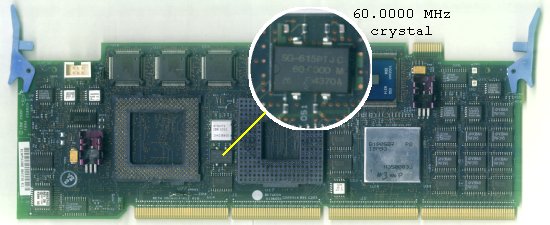
Position of the 60 MHz crystal oscillator
Against common believe this is no
simple crystal - it is an oscillator
chip with an integrated crystal and some electronic circuit in
one part. It runs on +5V and it generates the processor base clock
signal with a very high accuracy. The printing atop says '60.0000 MHz',
which is quite good and sufficient for e.g. a radio transmitter, which
safely keeps the frequency.
This chip is soldered to the printboard with 4 pins. They are +5V, GND
and output. The fourth pin is usually internally not connected,
sometimes (on those metal can types) it may be connected with the
shielding case and should be tied to GND as well.
The one on the Type-4 platform is a plastic style chip and
theoretically it should be easy to swap it out for a 66 MHz type.
For this purpose you need a solder iron and a wooden toothpick. Yes - a
toothpick. You need it as a lever to get it off. Start at one side and
warm up both pins alternating while gently trying to lift up
that side until both pins come up from the board. If you break
the toothpick during the operation you'd levered way too hard.
Therefore: don't use a screwdriver. If you apply too much power and
manage to get the chip off there is a good chance that the copper
contacts come with it and you'd successfully destroyed the board.
Once the one side has come free continue with the opposite side until
the chip is removed.
Now clean the contacts from the remaining solder tin. They need to be
evenly flat. "Mountains of Thing" make it hard to properly align the
new chip on the solder pads.
Align the new 66 MHz oscillator on these pads in proper direction with
the pin 1 bottom / left (or the case mark towards the CPU).
Then warm up the solder pad - not the pin until it starts to stick a
bit. Don't heat up the individual pins longer than a few seconds at one
time. Work around the other pins and make sure you have a good solder
spot on each.
That was it. Now you may want to replace the P90 CPU against e.g. a
P133 while you're at it. The P90 would be overclocked with a 66MHz base
clock and you better use a 133 type from now on.
The platform should come up like normal when you put it back into your
system. QCONFIG from PC-DOS 7 will nontheless claim the machine runs at
60MHz (it does not know better), but the "estimated CPU speed" will be
given as "99 MHz", which is the mathematically correct result from a 66
MHz base clock
and a 1:1.5 (or 2:3) multiplier ratio. Other programs like WinTune will
confirm that it runs at the correct speed.
There are oscillators available with 66.6666 MHz output. You may
use them too and will get 100 MHz straight, but that is fairly
unimportant. You are going to overclock the platform anyway if yours
got the 60 MHz rated cache RAMs and controller only.
I'd tried both with no major effect at all. Those platforms that worked
with the 66.0000 Mhz type worked with the 66.6666 MHz too and the final
result (in the test result pages) are of cosmetical value only - in
practice you see no difference.
Back up to the Top
|